Na Niemieckim Forum znalazłem ze można przepiąć piny w gniazdach.
Oto przykłady:
10 PIN - 12 PIN
4 - 7
5 - 11
6 - 4
7 - 6
8 - 8
9 - 5
10 - 3
=========================================
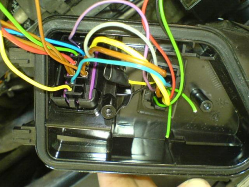
I jak to sie ma do pinów
10 pin Stock Wiring
1. Level Motor (+)
2. Front Fogs (+)
3. Negative (Level motor)
4. Negative (Low Beam, Indicators, Sidelights)
5. Level Motor Control (+)
6. Indicator (+)
7. Low Beam (+)
8. Negative (Front Fogs, High Beam)
9. High Beam (+)
10. Sidelight (+)
12 Pin Left Headlight
1. Black – Level Motor (+)/Purple – Levelling Controller (+)
2. K Wire à OBDII socket pin 7 or T32/25 (Blue plug on clocks)
3. Sidelight (+)
4. Indicator (+)
5. Main Beam (+)
6. Ballast (+)
7. Negative (Main Beam, Levelling Motor, Levelling Controller)
8. Negative (Ballast, Sidelight, Indicator)
9. Suspension Sensors (+). Pin 5 on both sensors (black wire)
10. Rear Suspension Sensor. Pin 4 (blue wire)
11. Levelling Motor Control
12. Front Suspension Sensor Pin 4 (red wire)
12 Pin Right Headlight
1. Level Motor (+) à T12a/1
2. K Wire à T12a/2
3. Sidelight (+)
4. Indicator (+)
5. Main Beam (+)
6. Ballast (+)
7. Negative (Main Beam, Levelling Motor)
8. Negative (Ballast, Sidelight, Indicator)
9.
10.
11. Levelling Motor Control à T12a/11
12.
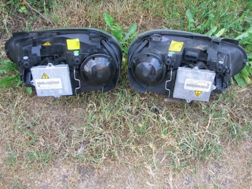
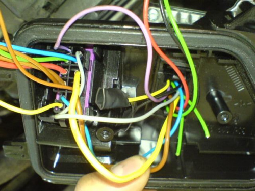
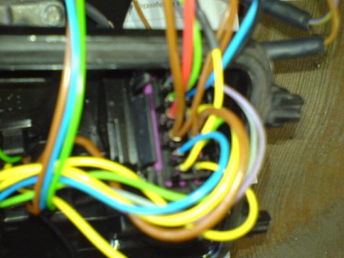
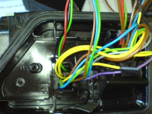
Tylko dlaczego do przetwornicy prócz kabli zasilających przychodzą 4 inne przewody, które są wpięte do kostki?
kulon-x Jak masz jakieś schematy to bardzo proszę o przesłanie. już wysłałem ci namiary.
Z góry wielkie dzięki. Każda pomoc sie przyda